
 Tiếng Việt


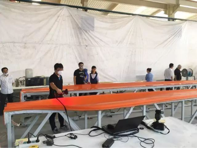
We use 3D scanning technology, including the DigiMetric 3D measuring system and the FreeScan X3 3D scanner, to inspect large parts at high speed.
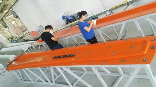 Applying reference markers is often the longest step when inspecting large parts like this one.
 A handheld 3D scanner can capture very large objects with very high accuracy.
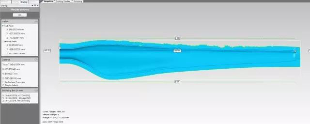
- See details of the FreeScan X3 3D scanner.
CONTACT
Contact CT3D Group
CT3D Group – professional 3D printing, 3D scanning, design and rapid prototyping services across Vietnam.
- CT3D Thu Duc – Ho Chi Minh City, Hanoi, Hai Phong: in3d.edu.vn – Hotline 0975 008 728 (Mr. Thai)
- CT3D District 6 – Ho Chi Minh City: 3dmaker.vn – Hotline 038 7798308 (Mr. Phuc)
Why use 3D scanning to inspect large wind turbine blades?
Wind turbine blades and large industrial fan blades have complex aerodynamic profiles: surfaces curve in several directions, the twist changes along the length, and the section gets thinner toward the tip. Measuring them with rulers, templates or a traditional CMM is slow and rarely covers the whole surface. A handheld 3D scanner combined with an optical photogrammetry system can capture millions of points across the entire blade in a short time, then compare them directly with the original CAD model.
Inspection workflow for large objects
- Preparation: clean the surface and apply reference markers evenly over the whole object. On very large parts this is usually the most time-consuming step.
- Reference frame measurement: use a photogrammetry system to capture coded targets and build an accurate coordinate frame. This limits error buildup when scanning long objects.
- Detail scanning: scan the surface with a handheld laser scanner, using the existing marker frame.
- Alignment and comparison: align the scan data to the CAD model’s coordinate system, generate a deviation color map, and check cross sections at the specified locations.
- Reporting: summarize deviations, out-of-tolerance areas and supporting images so the production team can act on them.
How the inspection data is used
Scan data is not only used to accept new parts. It also helps assess wear and deformation of blades after years in service, so you can decide whether to repair or replace them. For blades with no original drawings, scan data is the basis for reverse engineering and rebuilding the mold. The same method works for ship hulls, large molds, castings and steel structures. Companies that need to evaluate geometric deviation can look at our 3D inspection service with 3D scanners for clear color map reports.
Frequently asked questions
Is a handheld 3D scanner accurate on large objects?
Yes, with the right technique. On large objects, error can build up along the length, so a photogrammetry system is usually added to create a global reference frame and keep overall accuracy under control.
What is a color map in a 3D inspection report?
A color map shows the deviation between the scan data and the CAD model at each point. Green areas are usually within tolerance, while red and blue show where the part has excess or missing material compared with the design.
Do the blades need to be removed for scanning?
Not necessarily. A handheld scanner can be taken on site to scan in place, as long as the surface is accessible and the work is safe. Scanning in a workshop is usually easier in terms of lighting and scan angles, though.
Can you inspect a part without the original CAD file?
Yes. You can compare parts against each other or against a scanned reference part. The scan data can also be used to reverse engineer a CAD model that serves as the reference for future inspections.
Related services at CT3D Group
- 3D scanning service – high-accuracy 3D scanning
- 3D inspection service with 3D scanners
- Custom 3D printing service
- CT3D Group network: ct3dgroup.com · in3d.edu.vn – Hotline/Zalo 0975 008 728

